


Simulation & FEA Consulting
Decision-ready simulation support that reduces test iterations, de-risks design decisions, and shortens development cycles. From a single critical component to a wider workflow across assemblies, we define the right level of model fidelity and translate results into clear design actions.
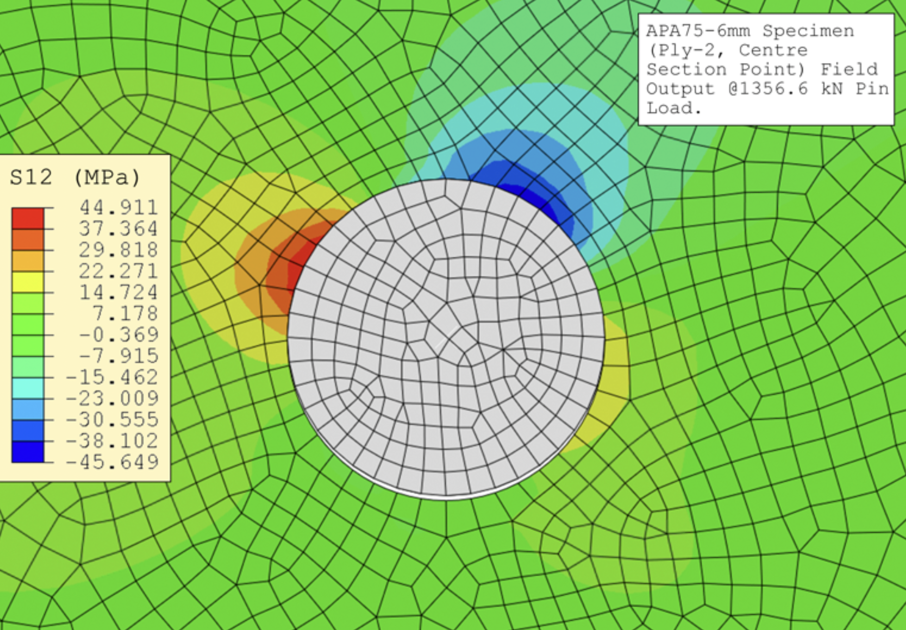
Typical projects: brackets and frames, bolted joints, composite sub-components, thermal distortion, vibration issues, and failure reconstruction—delivered as a clear decision pack with stated assumptions.
Choose how you’d like to continue.
STRUCTURAL CAPABILITIES
Open the items below to confirm scope. We choose the minimum model fidelity that answers the decision, then document assumptions and sensitivities.
We model contact interactions to assess load transfer, slip, separation, preload effects, and local stress concentrations.
Typical use-cases
Bolted joints, press fits, clamps, seals, assembled mechanisms.
We assess stability margins and sensitivity to imperfections where collapse or snap-through risk matters.
Typical use-cases
Thin-walled structures, panels, struts, lightweight frames.
We use simulation to recreate failure conditions and identify the dominant drivers, not just the symptoms.
Typical use-cases
Cracked brackets, yielding at features, unexpected deflection, field returns.
Where materials behaviour drives the decision, we include the necessary modelling detail (orthotropy, progressive damage indicators, etc.).
Typical use-cases
Composite coupons/sub-components, bonded joints, delamination risk screening.
We analyse resonances, mode shapes, dynamic amplification, and response under operational excitations.
Typical use-cases
Rotating equipment mounts, rattle/buzz issues, impact or transient loads.
We help you identify fatigue drivers and prioritise improvements using practical approaches suited to the available data.
Typical use-cases
Repeated duty cycles, crack initiation hotspots, design-for-life comparisons.
Where manufacturing drives performance, we assess distortion, residual stress, or interface changes that affect fit and strength.
Typical use-cases
Forming distortion, thermal processes, assembly-induced stresses.
We produce traceable outputs that support internal gates, customer reviews, or safety-case evidence packs (scope-dependent).
Typical use-cases
Regulated sectors, customer sign-off packs, “show your workings” reviews.
We run focused trade studies to quantify sensitivity and guide direction without over-modelling.
Typical use-cases
Thickness/material swaps, geometry variants, concept down-select.
MULTIPHYSICS CAPABILITIES
Use this when coupled physics materially affects the decision—otherwise we keep models simpler and faster.
We model the interaction between fluid motion and structural response where loads and vibrations are coupled.
Typical use-cases
Sloshing loads, flow-induced vibration, flexible structures interacting with flow.
We couple temperature fields to mechanical stress/distortion to predict thermal expansion effects and hotspots.
Typical use-cases
High-temperature components, thermal cycling, alignment/tolerance distortion.
We capture heat transfer across fluids and solids to evaluate thermal management end-to-end.
Typical use-cases
Cooling jackets, heat exchangers, electronics cooling and enclosure airflow.
We account for electrical/thermal loading interacting with mechanical constraints where safety/performance depends on coupling.
Typical use-cases
Battery pack risk screening, fuel cell/stack packaging constraints, heated components under structural load.
We connect system-level operating transients (duty cycles, controls) to local 3D behaviour so boundary conditions are realistic.
Typical use-cases
Transient loads informing local stress hotspots, thermal duty cycles driving fatigue risk.
TYPICAL OUTCOMES
Simulation should leave you with clearer, lower-risk decisions—not just plots.
- Reduce risk before prototype and test spend — validate critical behaviour early and avoid wasted build cycles.
- Improve strength / stiffness / weight trade-offs — quantify options so you can choose the right balance.
- Identify failure modes early and prioritise fixes — focus effort on the highest-impact issues first.
- Support design reviews with traceable evidence — decisions backed by clear assumptions and results.
DELIVERABLES
Outputs you can reuse internally and share with stakeholders with confidence.
- Decision-focused conclusions and recommended design changes — clear next steps you can act on.
- Clearly stated assumptions (loads, constraints, materials, safety factors) — so results are reviewable and defensible.
- Model files and notes suitable for internal reuse — handover outputs that survive team changes (where agreed).
- Technical reporting — concise summary or full report, matched to your stakeholders.
INPUTS & HANDOVER
Send what you have—we’ll fill any gaps with a minimal, agreed set of assumptions. Outputs are structured for reuse and auditability.
- Geometry: STEP/Parasolid (or drawings)
- Materials: datasheets / curves / spec
- Loads & constraints: operating scenario, boundary conditions, interfaces
- Success criteria: FoS, deflection, allowable stress/strain, life, pass/fail
- Context: test data, failure photos, field notes (optional)
- Interoperability: standard CAD interchange (STEP/Parasolid)
- Traceability: documented assumptions, BCs, and mesh approach
- Handover: structured pack for internal continuation (where required)
How We Work
We prioritise transparency—scope, assumptions, timelines, and change control are agreed up front, with phased delivery and regular checkpoints.
- Intro call (free, 30 min) — confirm goals, constraints, available data, and which standard package fits.
- Scope confirmation (included) — within 2 business days, you receive a 1–2 page Scope Confirmation: deliverables, inputs required, assumptions/exclusions, timeline, fixed price, and change control.
- Kickoff (60 min) — after acceptance, we run a technical kickoff to hand over data, confirm interfaces, and lock the delivery schedule.
- Delivery (phased) — work is delivered in short phases with a weekly written update: completed, next steps, questions, and risks.
- Review pack — you receive a draft pack for technical review (key results, assumptions, limitations, recommendations).
- Final handover — final report + agreed source files, plus a handover call.
FAQs
Short answers to the questions that typically block a decision to engage.
£4.5k is a typical entry point for a well-bounded component analysis with clear loads and success criteria. Multi-loadcase programmes, complex contact/non-linearities, extensive sensitivity work, or multiphysics coupling will usually be higher. We confirm scope and cost in the analysis plan before execution.
Yes—where geometry is straightforward. For complex parts, a STEP/Parasolid is preferred. If needed, we can agree a simplified model that still answers the decision.
Where data exists, we can calibrate or sanity-check model behaviour and highlight sensitivities that affect correlation.
We support established FEA workflows (including Abaqus/Ansys/SIMULIA), selecting the minimum fidelity needed to answer the question.
Yes, where agreed—along with notes on assumptions, boundary conditions, and how to rerun or extend the model.
We are NDA-friendly and use secure file handling. If you have a preferred NDA, we can work with it; otherwise we can provide one.
Often, yes—if the decision is narrow and inputs are ready. Use “Quick contact” and tell us the deadline.
GET IN TOUCH
Get in Touch.
Choose a quick note or share full project details—we’ll respond by email.
Quick contact — a short description and the decision you need to make.
Scope a project — share geometry, loads, deadline, and success criteria.